Special measurement tasks
Not every measurement object is „ideal“. Often you may face practical difficulties which might lead to negative influences on the measurement accuracy. Typical sources of errors are curved surfaces, rough substrate surfaces, measurements on edges or measurements on soft and sensitive coatings. Usually calibration of the gauge will result in a precise and reliable measurement value. On the following pages you will find a list of solution suggestions with respect to a few typical sources of Errors.

Measurements on curved surfaces
As opposed to measurements on flat surfaces, convex surfaces produce larger measurement values and concave surfaces produce smaller measurement values. This effect can be easily compensated with a calibration of the gauge. However Instruments do not need any additional calibration when measurements are made on surfaces whose curvature radii are larger than the reference values of the smallest convex curvature radii (rmin) listed in the table.
| r-min for steel/iron |
r-min for non-ferrous metals |
|
|---|---|---|
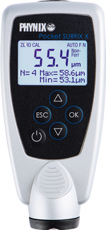
| Surfix® Pro S with 1.5mm probe Surfix® S with 1.5mm probe Surfix® E models Pocket Surfix® |
20 mm | 50 mm |
| Surfix® Pro S with 3.5mm probe Surfix® S with 3.5mm probe Surfix® easy |
30 mm | 75 mm |
| Surfix® Pro S with FN1.5/90° probe Surfix® S with FN1.5/90° probe |
25 mm | 65 mm |
| Surfix® Pro S with F10 probe Surfix® S with F10 probe |
50 mm | — |
With smaller curvature radii, an uncoated object should be tested having the same curvature to see whether the zero value or the measurement value can be accurately measured sufficiently with a calibration foil or whether a calibration must be carried out on the curved surface due to the excessive deviation.

Measurement on rough substrate surfaces
Roughness is the enemy of coating thickness measurement! If special measures are not taken, coatings on rough metal surfaces will always be measured too thick as compared to coating measurements on smooth surfaces.
Using our Surfix® instruments we recommend two methods which will enable you to extensively alleviate the influence of roughness. These methods make it possible to measure coating thickness over the peaks.
It is the coating thickness over the peaks which is of importance when assessing corrosion protection; this is why the measurement value over the peaks is of paramount importance. The uncoated rough surface must be accessible for both methods in order to calibrate
Method A (suitable for roughnesses with Rz smaller than 20μm):
- Zero the instrument: Position the probe approximately 10 times on the rough surface to carry out zeroing
- Carry out two-point calibration : Position the probe approximately 5 times for "foil calibration".
- You can now measure: Position the probe a number of times. The average value corresponds to the average coating thickness over the peaks
Methode B (suitable for roughnesses with Rz greater than 20μm):
- Instrument calibration on a smooth surface having the same shape and the same type of steel as the coated rough measurement object (one-point calibration or two-point calibration).
- Position the probe approximately 10 times on the rough uncoated measurement object and form the average value x0 ± s0 {xzero ± standard deviationZero} from the measurement values. This average value x0 is a measure for the roughness effect on the Coating Thickness Gauge. You can also use the statistic function of the instrument for averaging.
- Measurement of the coating thickness on the rough surface. Position the probe approximately 5 to 10 times on the coating to be measured. Determine the average value x0+C {xzero+coating} from the measurement values as described in Point 2. This average value x0+C is produced from the coating thickness plus the roughness effect.
- Calculate the difference from the average values x0+C - x0. The difference is the average coating thickness xC over the peaks
Example:
Step 2: x0 = 15μm, s0 = 5μm
Step 3: x0+C = 80μm
Step 4: xC = (x0+C - x0) ± s0 ± instrument tolerance
xc = (80µm – 15µm) ± 5µm ± (1µm +1% of the measurement value)
xc = 65µm +/- 7µm
The average coating thickness over the peaks is 65µm ± 7µm.

Measurement on edges
Coating thickness measurements near edges have a tendency to indicate larger measurement values, i.e. the actual coating is smaller than the displayed value. This effect occurs when the distance of the measurement point from the edge is smaller than the diameter of the probe.
The different probe diameters are shown in the table below:
| Probe / gauge | probe diameter |
|---|---|
| 1.5 mm probe (FN1.5, F1.5, N1.5), Surfix®, Pocket Surfix® | 5 mm |
| 90° probe (FN1.5/90°) | 6 mm |
| 3.5 mm probe (FN3.5, F3.5), Surfix® easy | 10 mm |
| 10 mm probe (F10) | 20 mm |
However, if a measurement is to be made distinctly nearer to the edge than the probe diameter then calibration is to be carried out on an uncoated part exactly at the required distance to the edge. This calibration will then eliminate any edge error.

Measurements on soft and sensitive coatings
The load pressure of approximately 0.3N can leave an indent with soft and sensitive coatings. A coating thickness will be indicated which is too low.
Tip: Place a piece of hard plastic foil (between 30μm/1.2mils and 100μm/4mils, e.g. one of our measurement foils) between the measurement pole of the probe and the coating in order to reduce pressure and measure the total thickness. Subtract the foil thickness from the measurement value.
