Principles for coating thickness measurement
Materials and components are coated for different reasons with a layer made out of a different material. Independent of the actual reason like protection or decoration, the measurement of the actual coating thickness of the applied material is very important. The PHYNIX gauges allow the non-destructive thickness measurement of coatings and use two different methods: the magnetic-inductive and the eddy-current principle:
- For non-destructive coating thickness measurement on iron and steel, i.e. ferro-magnetic substrates, the magnetic-inductive principle is used. The magnetic-inductive principle is employed in the models marked with F or FN (F=Ferro-magnetic) e.g. Surfix® FN. The coating must be non-magnetic – for instance, varnish, paint, enamel, plastic, glass, aluminium, lead, chrome, copper, brass, zinc, tin, etc.
- The eddy-current principle enables the non-destructive coating thickness measurement on non-magnetic metal substrates eg. aluminium, aluminium alloys, lead, bronze, copper, brass, zinc, die-cast zinc, tin. The Eddy current principle is used in models marked with N or FN (N=Non-Ferrous), e.g. Surfix® easy I-FN. The coatings under test must be electrically insulating; for instance, varnish, paint, enamel, plastic, glass, anodizing coatings and ceramics
Typical Applications for Coating Thickness Gauges using the Magnetic-Induction and the Eddy-Current Principle

All Surfix® models meet special international standards for thickness measurement:
- Method: DIN EN ISO 2808
- Magnetic-inductive method: DIN EN ISO 2178, ASTM B499, ASTM D7091
- Eddy current method: DIN EN ISO 2360, ASTM D7091
- Basic terms in measurement technology: DIN 1319, Teil 1 und Teil 3
Functionality of sensors
An exciter coil wrapped around an iron core and applied with a low-frequency alternating current is used for measuring according to the magnetic-inductive method (e.g. Modell Surfix® F). For this, a magnetic alternating field is generated in the air space around the poles.
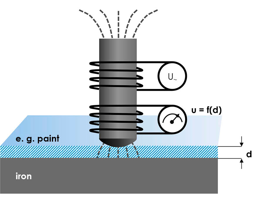
When a pole approaches an iron part, the magnetic field will be amplified. It then generates a voltage in a second coil (measuring coil). This voltage depends on the distance from the iron. By attaching the iron core or measuring sensor to the coating, a defined distance results between the pole and the iron, and thus a defined coil voltage. This is electronically evaluated and digitally displayed as the coating thickness.
Measurement according to the eddy current method uses only a single coil (e.g. model Surfix® N), through which a high-frequency alternating current flows. This produces an electromagnetic alternating field around the coil.
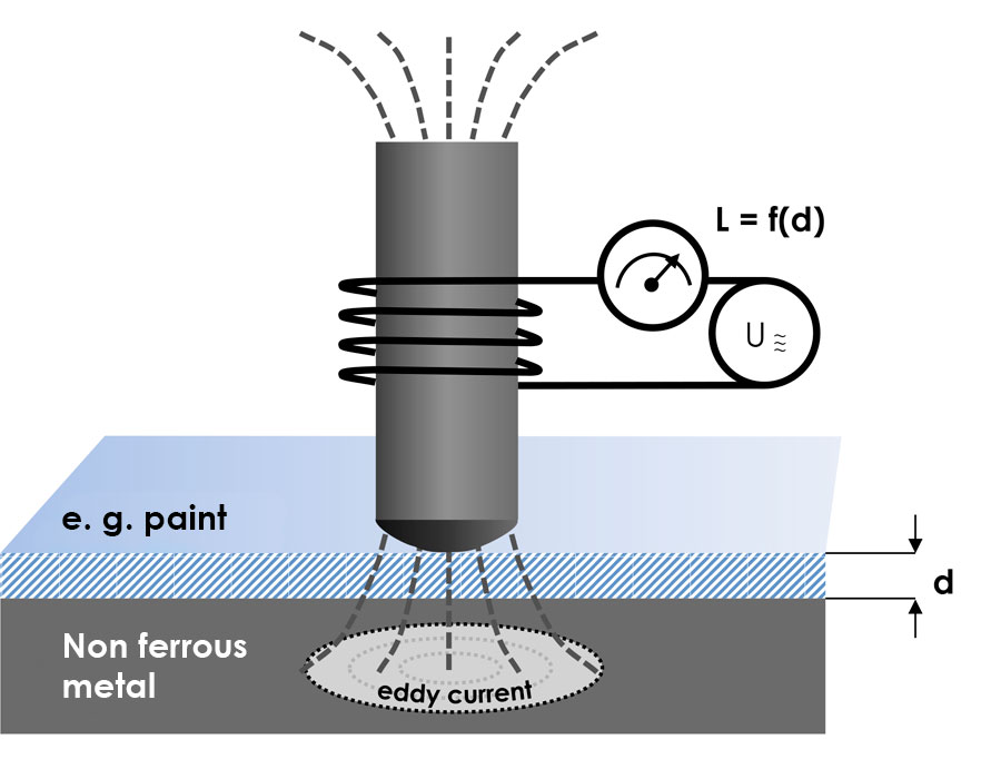
When the coil with its alternating field approaches a non-ferrous metal, an alternating current – called the eddy current – is induced in this metal. This produces another electro-magnetic alternating field in the opposite direction, weakening the original field. The effect in the coil is a change of inductiveness, a characteristic property of every coil. By applying the measuring sensor to the coating, a defined distance between the coil and the non-ferrous metal results, thus leading to a defined coil inductivity. This will be electronically evaluated and digitally displayed as coating thickness.
In the combination probes (e.g. model Surfix® FN), both coil systems are placed in the measuring sensor so that the alternating field of both coils – the low-frequency and the high-frequency alternating fields – are influenced when putting the sensor onto the object to be measured. The measuring signals of the two coils are automatically evaluated electronically with a microprocessor, so that the measuring procedure corresponding to the basic material can be selected and the correct layer thickness will be displayed, no matter if the measurement takes place on iron or non-ferrous metal.